
Welcome back to Ocsaly. In the previous chapter, we discussed the “Highways” of the modern vehicle. Now, we are getting tactical. To dominate the automotive space, you must move past theory and learn how to physically locate and decode the can bus communication protocol.
Hunting the 2.5V Signature
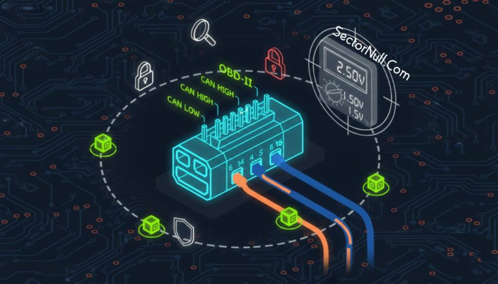
Finding a can bus in a sea of copper is easier than most people think. It is all about the “Resting Voltage.” CAN wires always run in dual wire pairs, twisted together to survive electromagnetic noise. When you hook up your multimeter, you are looking for a baseline of 2.5V.
When a signal is transmitted, the can protocol adds or subtracts 1V. This means CAN High will jump to 3.5V while CAN Low drops to 1.5V. If you find a twisted pair sitting at 2.5V at rest, you have found your target. On the standard OBD-II connector, these are locked to Pin 6 and Pin 14 for High Speed CAN (HS-CAN). However, remember that internal buses like the gmlan bus or mid speed lines may be hidden on other pins or require a direct tap into the harness.
Decoding the Can Bus Protocol Layout
Once you have tapped the lines using hardware like the mcp2515 and mcp2551, you will see a stream of raw data. This data follows a strict controller area network protocol frame.
The most critical part of a standard can a bus packet is the Arbitration ID. This broadcast message identifies which device is talking. Because the canbus is a priority based system, the lower the ID number, the higher the priority on the line.
A standard packet contains:
- Arbitration ID: 11-bit identifier.
- IDE: Identifier Extension bit (always 0 for standard).
- DLC: Data Length Code (0 to 8 bytes).
- Data: The actual payload.
Extended Packets and ISO-TP
For more complex systems, we see extended packets which use a 29-bit identifier. These are backward compatible with standard can network protocol frames but allow for millions of more IDs.
When 8 bytes of data are not enough, we move into the iso-tp protocol (ISO 15765-2). This is used for diagnostics and large data transfers, allowing us to chain packets together to send up to 4095 bytes. Be careful when sniffing iso-tp; sending large transfers can easily flood the bus and cause latency in critical systems.
Proprietary Standards: GMLAN and CANopen
Manufacturers often implement their own flavors of the can bus communication protocol.
- GMLAN Bus: General Motors uses a single wire low speed bus (33.33Kbps) for non critical “comfort” data and a dual wire high speed bus (500Kbps) for the heavy lifting.
- CANopen Protocol: Seen more in industrial settings, this uses a 4-bit function code and a 7-bit node ID. If you see Arbitration IDs starting with 0x0, you are likely looking at a CANopen implementation.
How This Interactive CAN Bus Lab Works
This lab is a software simulation of a physical CAN bus, designed to help you understand what actually happens on the wire when electronic control units communicate inside a vehicle or industrial system.
CAN does not transmit data using a single voltage line. Instead, it uses differential signaling across two wires:
- CAN High (CAN_H)
- CAN Low (CAN_L)
The logic state of the bus is determined by the difference between these two voltages, not by their absolute values. This is the key concept this lab is designed to teach.
Recessive vs Dominant States
When the bus is idle, both CAN_H and CAN_L sit at approximately 2.5 volts.
This is called the recessive state.
In this state:
- No node is actively driving the bus
- The differential voltage is effectively zero
- Logical value transmitted is a one
When a node transmits a dominant bit, it actively forces:
- CAN_H upward
- CAN_L downward
This creates a voltage difference large enough that every node on the network can reliably detect it.
In real systems, this dominance property is critical because:
- A dominant bit always overrides a recessive bit
- Arbitration works without data corruption
- Multiple nodes can attempt transmission safely
This lab lets you see that dominance visually and numerically.
What You Are Seeing in the Voltage Display
The voltage boxes show three values in real time:
- CAN_H voltage
- CAN_L voltage
- Differential voltage (CAN_H minus CAN_L)
The differential value is the most important one.
Even if both wires experience electrical noise, as long as the difference remains detectable, communication survives. This is why CAN is so resilient in noisy environments like vehicles and factories.
How to Interact With the Lab
You are not meant to just click buttons randomly. Each control represents a real-world bus condition.
Recessive (Idle)
Sets both lines to the same voltage.
Use this to establish a baseline and observe zero differential voltage.
Dominant Bit
Simulates a node actively transmitting.
Watch how CAN_H and CAN_L separate and how the differential voltage increases.
This is how logical zeros are physically encoded on the bus.
Inject Noise
Simulates voltage fluctuation caused by electromagnetic interference.
Notice that the bus still functions because the voltage difference is preserved.
This demonstrates why CAN uses differential signaling instead of single-ended logic.
Bus Short Fault
Simulates a catastrophic failure where both lines collapse.
This shows what happens when physical integrity of the bus is lost.
This is not a protocol problem. It is an electrical failure.
Why This Matters for Security and Analysis
From a security and reverse engineering perspective, understanding this physical behavior is not optional.
If you are:
- Sniffing CAN traffic
- Injecting messages
- Diagnosing bus instability
- Investigating fault conditions
- Performing vehicle penetration testing
You must understand what the bus looks like electrically, not just at the frame level.
Many attacks fail not because the protocol logic is wrong, but because the attacker does not respect:
- Dominance rules
- Timing
- Voltage behavior
- Physical layer constraints
This lab gives you intuition that packet diagrams alone cannot provide.
How to Use This Lab Effectively
Do not rush through it.
- Change one state at a time
- Observe voltages before reading the explanation
- Predict what should happen, then verify
- Ask yourself what a real ECU would see at that moment
If you can explain why each button produces its effect, you understand the CAN physical layer well enough to move forward.
If you cannot, stay here and keep experimenting.
That is the point.
CAN BUS LAB 01: Differential Signaling Fundamentals
This interactive lab demonstrates how Controller Area Network uses differential voltage signaling to represent logical states. You will actively manipulate the bus and observe how voltage levels translate into dominant and recessive bits.
Learning Objectives
- Understand CAN_H and CAN_L voltage behavior
- Observe dominant vs recessive bit states
- Calculate differential voltage in real time
- Recognize fault conditions on a CAN bus
Live Bus Voltage Monitor
2.5 V
2.5 V
0.0 V
Waveform Representation
CAN_L: ───────