
Finally, the “Unproblematic” CAN Fuzzer is alive!
After spending way too much time staring at logic analyzers and wondering why my ESP32 was being such a silent brat, I finally got the bridge working. Honestly, the commercial tools for this are a total joke – some of them cost 200 Euros just for a basic sniffer, and the “pro” gear goes into the thousands. It’s a complete rip-off when you realize you can build something just as fast (and honestly, more transparent) for about 20 bucks.
But as I always say: buying a tool gives you a result, but building one gives you the knowledge. And man, did I learn a few things the hard way with this one.
The “Red Wire” incident and the 3-Wire Rule
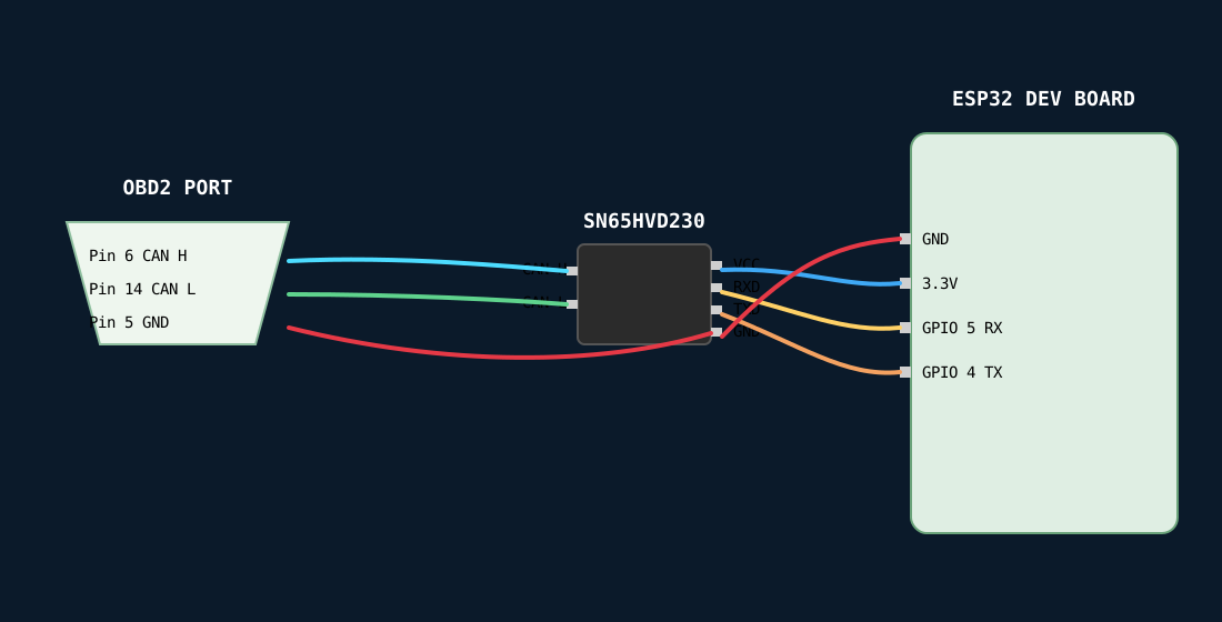
First off, let’s talk about the hardware. I’m using a Wemos D1 R32 (basically an ESP32 that thinks it’s an Arduino) and an SN65HVD230 transceiver. One thing that annoyed me right off the bat: my wire stash was looking pretty pathetic. I only had a couple of black wires and one red one.
Normally, red means “danger” or “power,” but in this build, I decided to make the Red wire the Signal Ground. If you’re following along at home, label your damn wires. If you forget that red is ground and plug it into a 12V source, you can kiss your ESP32 goodbye.
The schematic is simple enough, but don’t get sloppy:
- CAN High/Low: The two black wires. Twist them together! It looks cooler, and it actually helps cancel out the electrical noise from your car’s alternator.
- The Bridge: You MUST connect the ground from the OBD2 (Pin 5) to both the transceiver and the ESP32. Without this “common ground,” your data will look like random garbage or, worse, you’ll see 6V spikes that will make your chip run hot enough to fry an egg.
Soldering Advice (Learn from my mistakes)
I’ve ruined my fair share of pads by being impatient. When you’re soldering to those tiny pins on the transceiver or the OBD2 connector, remember the 3-second rule. Heat the pin, touch the solder, and get out. If you linger too long, you’ll melt the plastic housing of the connector, and it’ll never sit flush in your car again.
Also, tin your wires first. It makes the final joint happen almost instantly. Since cars are basically vibrating metal boxes, a “cold” solder joint will fail the moment you hit a pothole. I used a bit of hot glue (classic, I know) to act as strain relief for the cables. It’s not winning any beauty contests, but it keeps the vibrations from ripping the wires off the PCB.
WIRING :
Alright, let’s get the wiring sorted. If you mess this up, you’re either going to be staring at a blank screen or smelling burnt silicon, so pay attention. We’re working with two black wires for the data and a red one for ground. Since the colors are unconventional, you have to be your own quality control here.
1. The OBD2 Side (The Source)
Flip that male OBD2 connector over so you’re looking at the solder cups. You need to hit exactly three pins. Don’t guess—count them twice.
- Pin 6 (CAN High): Solder your first Black wire here. Label the other end with a piece of tape marked “H.”
- Pin 14 (CAN Low): Solder your second Black wire here. Label the other end “L.”
- Pin 5 (Signal Ground): Solder your Red wire here. This is our “Zero” reference.
Technician’s Note: Use Pin 5, not Pin 4. Pin 4 is chassis ground and it’s full of electrical noise from the wipers and alternator. Pin 5 is the clean signal ground meant for data.
2. The Transceiver (The Interpreter)
Now take those 2-meter leads to the SN65HVD230. If your module has screw terminals, strip about 5mm of insulation, tin the tips with solder so they don’t fray, and crank them down.
- CAN H Terminal: The Black wire labeled “H.”
- CAN L Terminal: The Black wire labeled “L.”
- GND Pin: The Red wire.
3. The Logic Link (To the ESP32)
This is where the “Bridge” happens. You need four short jumpers between the SN65 and your Wemos R32.
- VCC to 3.3V: Powers the chip. Once you plug in the USB, that green LED on the SN65 better be glowing.
- GND to GND: Connect the SN65 ground to the ESP32 ground. Crucial: Your Red wire from the car must also tie into this same ground point. Everything—the car, the chip, and the ESP32-must share this one common ground or the data pulses won’t make sense to the processor.
- CTX to IO4: This is your transmit line.
- CRX to IO5: This is your receive line.
4. The “Anti-Headache” Physical Check
Before you even think about plugging into the car:
- Twist the Blacks: Take the two 2-meter black wires and twist them together tightly all the way down the length. This creates a “Twisted Pair” which cancels out electromagnetic interference.
- Strain Relief: Use a dab of hot glue or a zip-tie where the wires meet the board. If you trip over the cable in the car, you want the glue to take the hit, not your solder joints.
- The Tug Test: Give every wire a firm tug. If it wiggles, your solder joint is garbage. Re-flow it until it’s shiny and solid.
That’s it. Three wires to the car, four to the board, and one shared ground to rule them all.
The “Transparent” Firmware
I wanted this code to be as raw and fast as possible. No bulky libraries, no WiFi overhead, just pure serial speed. I’m using the native TWAI (Two-Wire Automotive Interface) driver because it’s built into the ESP32 silicon.
I’ve set the Serial baud rate to 921600. Yeah, it’s fast, but when a Toyota Prius starts screaming thousands of messages a second, 115200 baud just can’t keep up. You’ll start dropping frames, and when you’re trying to find the exact ID for a hazard light, missing one frame means you’re back to square one.
#include <Arduino.h>
#include "driver/twai.h"

// Configuration
static const gpio_num_t CAN_TX_PIN = GPIO_NUM_4;
static const gpio_num_t CAN_RX_PIN = GPIO_NUM_5;

// Buffer for incoming Serial commands from SavvyCAN
String inputBuffer = "";

void handleSavvyCANTransmit(String cmd) {
    // Basic slcan 't' command validation: tIIIL... (t + 3-hex ID + 1-digit DLC)
    if (cmd.length() < 5 || cmd[0] != 't') return;

    twai_message_t tx_msg;
    memset(&tx_msg, 0, sizeof(tx_msg)); // Clear memory to prevent garbage data

    // Parse ID (3 hex digits)
    tx_msg.identifier = strtol(cmd.substring(1, 4).c_str(), NULL, 16);

    // Parse DLC (1 digit)
    tx_msg.data_length_code = cmd.substring(4, 5).toInt();
    if (tx_msg.data_length_code > 8) tx_msg.data_length_code = 8;

    // Parse Data Bytes
    for (int i = 0; i < tx_msg.data_length_code; i++) {
        tx_msg.data[i] = strtol(cmd.substring(5 + (i * 2), 7 + (i * 2)).c_str(), NULL, 16);
    }

    // Attempt to transmit
    esp_err_t res = twai_transmit(&tx_msg, pdMS_TO_TICKS(5));

    // Debug: If transmission fails, it's usually because the bus is noisy or disconnected
    if (res != ESP_OK) {
        // Optional: Serial.println("!ERR:TX_FAIL");
    }
}

void setup() {
    // Use 115200 for standard slcan, though 921600 is better for high-traffic fuzzing
    Serial.begin(115200);

    twai_general_config_t g_config = TWAI_GENERAL_CONFIG_DEFAULT(CAN_TX_PIN, CAN_RX_PIN, TWAI_MODE_NORMAL);
    twai_timing_config_t t_config = TWAI_TIMING_CONFIG_500KBITS(); // Prius Primary Bus Speed
    twai_filter_config_t f_config = TWAI_FILTER_CONFIG_ACCEPT_ALL();

    if (twai_driver_install(&g_config, &t_config, &f_config) == ESP_OK) {
        twai_start();
    }
}

void loop() {
    // 1. RECEIVE FROM CAR -> SEND TO SAVVYCAN
    twai_message_t rx_msg;
    // Process all pending messages in the hardware buffer
    while (twai_receive(&rx_msg, 0) == ESP_OK) {
        if (!(rx_msg.flags & TWAI_MSG_FLAG_RTR)) {
            Serial.printf("t%03X%d", rx_msg.identifier, rx_msg.data_length_code);
            for (int i = 0; i < rx_msg.data_length_code; i++) {
                Serial.printf("%02X", rx_msg.data[i]);
            }
            Serial.print('\r'); // SavvyCAN uses Carriage Return as the end-of-frame marker
        }
    }

    // 2. RECEIVE FROM SAVVYCAN -> SEND TO CAR
    // Non-blocking serial read
    while (Serial.available()) {
        char c = Serial.read();
        if (c == '\r') {
            handleSavvyCANTransmit(inputBuffer);
            inputBuffer = ""; // Reset buffer for next command
        } else if (c != '\n') { // Ignore newlines
            inputBuffer += c;
        }
    }
}Sitting in the car at midnight with a glowing green LED on your breadboard is a pretty great feeling. I’ve already managed to sniff out the hazard light codes on my 3rd Gen Prius, though my VW Golf is being much more stubborn thanks to its gateway firewall.
If you’re on Linux and the Arduino IDE is giving you “Permission Denied” errors, just run sudo chmod a+rw /dev/ttyUSB0 and stop crying. It’s a 5-second fix.
Next up, I’m going to start mapping out the battery SOC (State of Charge) IDs. If anyone has a lead on the Prius 2010 PID list, I’m all ears!
Stay unproblematic.