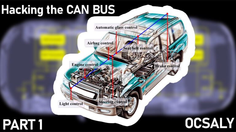
Hacking The CAN Bus
Understanding the CAN-standard vehicle network is vital to a successful engine swap involving any U.S.-market vehicle or engine built after 2007 and some vehicles or engines built much earlier, starting with the 1986 BMW 850 coupe. Engine data broadcast on the CAN by the engine control module may be required by other embedded controllers to work properly.
Obvious examples include rpm data that’s required by a dash controller to operate the tachometer, vehicle speed data required by a body control module to lock or unlock the doors above a certain speed, or engine rpm, manifold pressure, and vehicle speed required by a transmission control module to shift the gears of an electronic automatic transmission.
Bosch pioneered the controller area network (CAN) serial data-link protocol in the early 1980s and licensed a number of semiconductor vendors to develop and produce controller chips.
Twenty-five years later, starting in 2008, the U.S. government required all cars sold in the U.S. to support CAN protocol for OBD-II diagnostics. CAN specified what’s called the data-link layer of a networking protocol stack, and left the physical layer and all higher layers open to be implemented by automakers as they saw fit. CAN does, however, specify that the physical layer must support an active (i.e., dominant) state for a zero bit and a passive (i.e., recessive) state for a one bit, which is critical to resolving collisions between messages of differing priority. Many organizations have developed differing physical layers that support CAN. GM, for example, developed GMLAN, are presentative onboard network which defines two physical layers along with the higher level layers that provide standards by which all of a vehicle’s various processors or nodes cooperate to accomplish diagnostic, bulk data transfers, ECU reflash or recalibration, and so forth. CAN uses a Non-Return-to-Zero protocol, NRZ-5, with bit stuffing, and the network implements. Carrier Sense Multiple Access with Collision Resolution(CSMA/CR). GMLAN consists of two linked CAN buses: ahigh-speed dual-wire CAN for high-speed (EMS and brake)nodes and a lower-speed single-wire CAN for other nodes (in some cases there may be a medium-speed bus). The primary purpose of GMLAN was to improve reliability and lower costs by reducing the numbers of wires, connections, and special purpose circuits in a vehicle. GMLAN promotes synergism between vehicle nodes to provide features that would not be feasible without a network. CAN does not include addresses in the traditional sense, but is a publish-and-subscribe communications module. Each packet is physically broadcast to all nodes, which decide for themselves whether to process the message packets. Packets include no authenticator fields, meaning any embedded controller can indistinguishably send a packet to any other. There is a defined challenge-response sequence designed to protect the system against certain actions without authorization. Thus a given ECU may participate in zero, one, or two challenge response pairs for: re flashing and memory protection (for upgrading the firmware), and tester capabilities (on GM, Device Control diagnostic service used during manufacturing and servicing operations).
Normal messages are the messages broadcast between controllers. Data varies depending on the electronics systems, and being undefined by CAN/OBD-II, is defined by vehicle manufacturers, most of which have taken a similar approach. Normal message data does not need to be requested but is typically sent at a periodic rate by a controller as fast as it needs to be sent so that listening controllers get a timely value.
Diagnostic messages are command/response messages. If you want to get data from an embedded controller, you have to send it a request. The controller will then respond to that request using a common diagnostic protocol. There are only a handful of protocols that are used and these are typically specific to the OEM; however, there is not much difference between OEMs on how they have implemented their flavor of diagnostic messages.
Device Control protocol takes an argument (parameter)called a control packet identifier, which specifies a group of controls to override. Device Control is used for situations that require exporting control commands from one ECU to other embedded controllers on the CAN bus.
The OBD-II Connector typically has access to all of the vehicle’s onboard networks so that engineers and techs working on the vehicle can access the data easily. When the vehicle is released from manufacturing, the networks usually remain accessible from the OBD-II connector, though there have been cases where a
gateway device was installed to block hackers from accessing all CAN data from the OBDII connector—which was the situation with some Fiat Chrysler vehicles. In such cases, access to the powertrain or body CAN buses, requiring finding the appropriate bus somewhere on the vehicle and tapping into the one- or two wire (or fiber-optic) network. Happily, FiatChrysler has phased out the gateway, at least in some cases. The body network of the 2011 Town and Country is accessible on pins 3 and 11 of the OBD-II connector and could be found as well on the OBD-II connector of the new Fiat 500 destined for the U.S. marketplace.