Among the most common of questions asked about fuel injection systems is, “How do I know where I’m at in the table at any given time?” The answer is, of course, “It depends.” Fortunately, the main tables usually use a common set of axes. The most common is speed in engine RPM and load in either kPa of manifold pressure or percent filling. The combination of speed and load tells the ECU a lot about what the engine is being asked to do. To make this easier, let’s break the base maps down into “zones” and explore what’s going on in each of them. The chart on this page shows a typical volumetric efficiency map divided into several zones. This could just as easily be demonstrated with a spark advance or commanded air/fuel ratio map, but we’ll discuss all three as we walk through the different zones. The zones may overlap slightly, and boundaries shown are not absolutes for all engines.
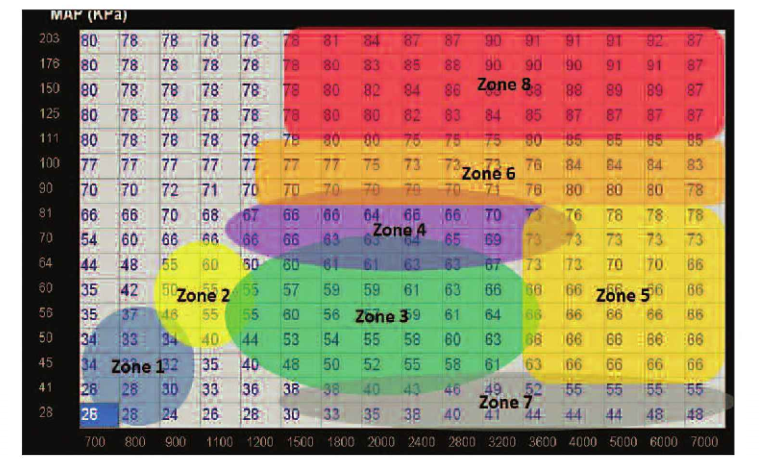
By dividing the VE map into several zones, we can get a better idea of what’s going on with the engine. Each numbered zone represents a different operating condition for the vehicle and will have its own priorities for fueling and spark.
Zone 1 The first zone is the idle region. Centered around the target idle speed and nominal idle vacuum, it represents the lowest running speed of the engine and a point where most engines spend a great deal of time. Air/fuel ratio is typically held around lambda=1.0() for both emissions and fuel economy. Within this zone, the engine speed and load may vary slightly as the vehicle is pulled into
gear without yet moving or as accessories like air conditioning and power steering are cycled. Through all of this, stalling is not allowed and measures must be taken to prevent it at all costs. Smooth control of idle speed is executed by adjusting both airflow and spark advance in an effort to deliver smooth, consistent operation.
Zone 1 is the engine’s normal idle range. Throttle is closed and timing is manipulated to maintain a steady torque output equal to the sum of the losses in the system at the target speed.
Zone 2 represents the tip-in area. After idle, this is the next point drivers will experience with the engine. Air/fuel ratio should remain at lambda—I .00, even as this zone is entered in a transient condition. Doing sg requires two things. First, the airmass estimation in this region at steady state must be correct. The steady state airmass at each cell within this zone represents the target airflow. If this target airmass is not clearly defined, it’s almost impossible to get the fuel mass there on the fly with any accuracy. Second, the transient fueling corrections must be sufficient to cover the changes in actual cylinder fueling compared to fuel added directly at the injector. There are usually a set of additional tables to compensate for transient fueling, but having the Zone 2 VE table values correct in the first place makes tuning the transient fuel tables later that much easier. Ignition timing in these cells should be set to MBT to provide maximum torque response as the driver performs a tip-in.
Zone 3
Zone 3 is the cruise area. Engines will spend a lot of time here, especially when driving at a relatively steady speed with minimal road grade. Within this zone, the cylinders are typically only being filled about 20 to 30% of their maximum
Zone 3 is the cruise region. Most engines spend a great deal of time here and should be calibrated to operate at lambda=l .00 within this range to improve fuel economy and emissions.
on a mass basis, fairly light load. This zone should get a lot of attention during the calibration process since it has such a profound impact upon the “feel” of the car as well as the fuel economy and emissions. Air/fuel ratio is set to lambda=l .00 through- out this region to promote good emissions and decent fuel economy. Spark knock is usually not a concern in this zone. Timing should be carefully tuned to MBT at as many of these points as possible to improve the mechanical efficiency of the cycle. By running at MBT at each of these points, the engine delivers the most torque possible for the same amount of air and fuel being burned. If this torque is more than the driver needs, he will instinctively reduce the pedal position, which in turn reduces the cylinder load and fuel consumption to a lower point. This lower point should also be similarly optimized for timing and torque so that, at any given point, the driver is only burning the minimum amount of fuel necessary to generate the desired torque needed to push the vehicle down the road.
This goes a long way toward improving fuel economy and should get the appropriate amount of attention during the calibration process.
Zone 4
Zone 4 correlates to a region of moderate acceleration on level roads to steady driving on a grade. The cylinder loading and delivered torque are both slightly greater than Zone 3, but not yet high enough to warrant a full power strategy. Air/fuel ratio remains at a target of lambda—I .00 and timing is still set to MBT as long as knock is not present. With a properly engineered engine system, component temperatures should not be an issue yet.
Zone 4 shows moderate acceleration or driving against a increased load such as on a grade or when towing. Output torque and engine cooling become a greater concern here.
Zone 5
Zone 5 lies in an area where most drivers hopefully don’t spend very much time. It is an elevated engine speed, but with only moderate loads such as leaving the engine in a lower gear on purpose. Most automatic transmissions will not allow the engine to operate here unless the driver has specifically selected the lower gear. Road racers may spend time here as they heel-toe downshift or hold a lower gear through a long, sweeping corner. In this condition, the added engine RPM can contribute to higher component temperatures, so some cooling strategies may be set in motion. Exhaust valves, catalysts, and exhaust manifolds in particular will be subject to high temperatures if the engine is run here continuously at lambda—I .00, so some enrichment is typically added to help bring combustion and exhaust gas temperatures down. Values Of anywhere between and lambda=0.8S may be necessary to control temperatures, depending on the system. Ignition timing should still be significantly advanced in Zone 5. The lighter load and higher speed both point to the need for numerically larger spark advance values. Don’t be afraid to use what looks like really high ignition timing values here as long as no knock is present. Overly retarded ignition timing in this zone will have a large amount of fuel burning late in the exhaust stroke and as it travels down the runners, releasing the heat to the sensitive exhaust components instead of to the water-cooled cylinders, where it would otherwise be better absorbed. Too little timing here can quickly overheat and fail even the best exhaust components.