Hacking into an automotive control module far enough to retrieve its current firmware and configuration is really just the beginning of the adventure. At this point, you probably have anywhere from 4KB to 4MB of raw machine-ready code, with a mixture of various parameters and actual code that forms the program the processor will run.
First, you must know which chip this binary is for. There are several free decompilers for different chips out on the Internet. Otherwise you can drop some cash and buy IDA Pro, which supports a large variety of chips. These tools will convert the hex values in the binary into assembler instructions. The next stage is to figure out what exactly you are looking at. When you’re starting to analyze raw data, a high-level understanding of the function of the devices you’re reverse engineering will be key to knowing what to look for. You can follow a number of breadcrumbs, or clues, for starters; these breadcrumbs are almost guaranteed to lead you to interesting and useful material. Next, we’ll look at a few specific examples of how to use common automotive controller functions to gain insight into their operation, which will hopefully allow us to change their behavior.
Self-Diagnostic System Every engine controller has some type of self-diagnostic system that typically monitors most critical engine functions, and analyzing this is an excellent route to understanding firmware. A good first step in investigative disassembly is to identify the location of these procedures. This will provide you with insight into the memory locations involved in all of the sensors and functions that are checked for errors. Any modern vehicle should support OBD-II packets, which standardize the diagnostic data reported.
Even controllers created prior to OBD-II standards have a way to report faults. Some have a system where an analog input is shorted to ground and either an internal LED or the “check engine” light flashes out the code. For example, knowing that code 10 refers to a failed intake air temperature sensor means you can find the piece of code that sets error code 10 to help you identify the internal variables associated with the air temperature sensor.
Library Procedures
Being able to change the behavior of a control unit is often one of the primary goals of reverse engineering ECU firmware, and identifying data used by a controller is an important step in the process. Most ECUs have a set of library functions used for routine tasks throughout the code. Library functions used for table lookups are worth identifying early on in the reverse engineering process, as these can lead straight to the parameters you’re interested in. Each time a table is used, a function is called to fetch a result. Calls to this type of function are among the most frequent, making them easy to spot.
(Subscribe for More Videos)Also Take a Look :
Usually each type of data stored within the ECU—one-dimensional array of bytes; two-dimensional array of words; three-dimensional array of unsigned, signed, and float shorts; and so on—has a unique reference function. When called, each table lookup routine needs to be passed, at a minimum, the table index (or start address) and the axis variables. Often, table lookup routines can be reused to pass information about the structure of the table, such as how many rows and columns are present. Calibration data is usually stored in program memory, along with the routines accessing them. Microcontrollers typically have special instructions to access program memory, which provide a unique signature to search for and make table lookup routines particularly easy to spot. A secondary characteristic of these lookup routines is that they tend to have lots of interpolation math. In addition, table lookup routines are often grouped closely together in program memory, making it even easier to find others after you’ve found one. After identifying reference routines, searching for all calls to them can provide a key to identifying the vast majority of data used by the controller to make decisions. The arguments passed to these functions typically include the start address of a table, its structure or shape, and which variables index elements of the table. Armed with this information, you’re much closer to being able to change the behavior of the controller.
Finding Known Tables
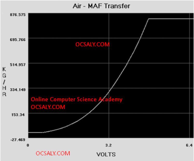
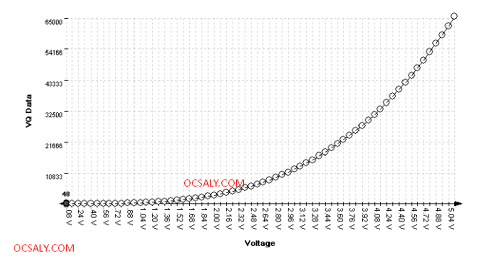
One way to identify tables is to leverage the specific physical and electrical characteristics of vehicle sensors, which will display identifiable characteristics within ECU firmware. For example, an ECU with a MAF sensor will have a table that translates raw readings of voltage or frequency from the MAF into airflow into the engine, providing an internal representation. Fortunately for us, the signal output from an MAF is determined by physics—that is, King’s Law—so the curve will always have a characteristic shape, though it’ll be slightly different for each sensor. This will result in the tables having a characteristic set of values that can be observed in the ROM.Armed with the knowledge that there will be universal data to identify, let’s take a closer look at how calibration data is displayed in different programs. This Picture show similarly shaped BMW and Mercedes sensor curves; the similarity they illustrate extends to multiple manufacturers.
Program Link : https://github.com/blundar/analyze.exe/
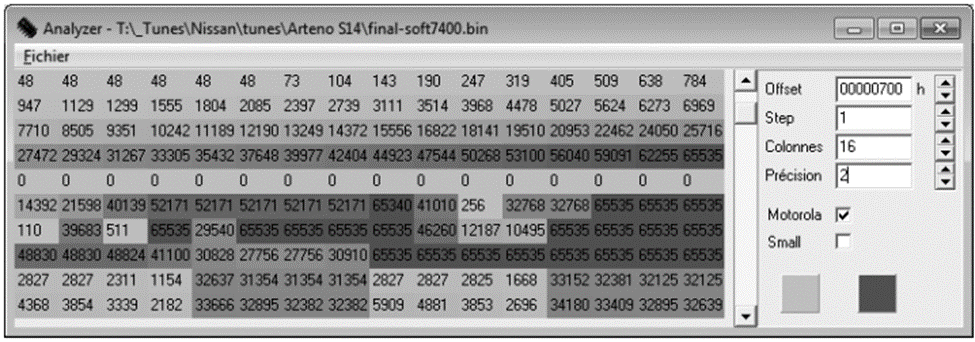
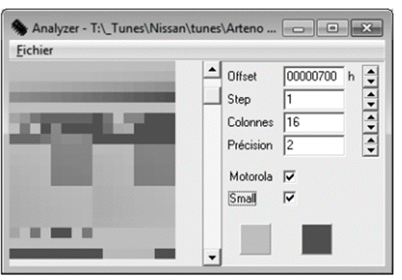
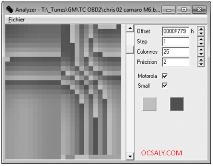
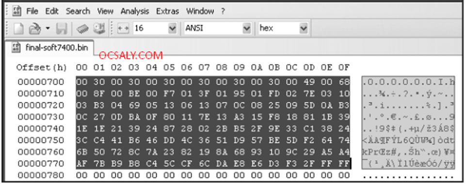
Data visualization tools like hex editors or analyze.exe can also be useful when you don’t know the exact shape or pattern you are looking for. No matter what type of vehicle you’re looking at, data structures will have orders and patterns that are not typically seen in executable code. This Picture shows an example of the clear visual pattern of data in analyze.exe—gradually changing values and repetition should stand out.