
The Flexray bus
FlexRay is a high-speed bus that can communicate at speeds of up to 10Mbps. It’s geared for time-sensitive communication, such as drive-by wire, steer-by-wire, brake-by-wire, and so on. FlexRay is more expensive to implement than CAN, so most implementations use FlexRay for high-end systems, CAN for midrange, and LIN for low-cost devices.
Hardware
FlexRay uses twisted-pair wiring but can also support a dual-channel setup, which can increase fault tolerance and bandwidth. However, most FlexRay implementations use only a single pair of wiring similar to CAN bus implementations. Network Topology FlexRay supports a standard bus topology, like the CAN bus, where many ECUs run off a twisted-pair bus. It also supports star topology, like Ethernet, that can run longer segments. When implemented in the star topology, a FlexRay hub is a central, active FlexRay device that talks to the other nodes. In a bus layout, FlexRay requires proper resistor termination, as in a standard CAN bus. The bus and star topologies can be combined to create a hybrid layout if desired.
Implementation
When creating a FlexRay network, the manufacturer must tell the devices about the network setup. Recall that in a CAN network each device just needs to know the baud rate and which IDs it cares about (if any). In a bus layout, only one device can talk on the bus at a time. In the case of the CAN bus, the order of who talks first on a collision is determined by the arbitration ID. In contrast, when FlexRay is configured to talk on a bus, it uses something called a time division multiple access (TDMA) scheme to guarantee determinism: the rate is always the same (deterministic), and the system relies on the transmitters to fill in the data as the packets pass down the wire, similar to the way cellular networks like GSM operate. FlexRay devices don’t automatically detect the network or addresses on the network, so they must have that information programed in at manufacturing time. While this static addressing approach cuts down on cost during manufacturing, it can be tricky for a testing device to participate on the bus without knowing how the network is configured, as a device added to your FlexRay network won’t know what data is designed to go into which slots. To address this problem, specific data exchange formats, such as the Field Bus Exchange Format (FIBEX), was designed during the development of FlexRay.
FIBEX is an XML format used to describe FlexRay, as well as CAN, LIN, and MOST network setups. FIBEX topology maps record the ECUs and how they are connected via channels, and they can implement gateways to determine the routing behavior between buses. These maps can also include all the signals and how they’re meant to be interpreted. FIBEX data is used during firmware compile-time and allows developers to reference the known network signals in their code; the compiler handles all the placement and configuration. To view a FIBEX, download
FIBEX Explorer from http://sourceforge.net/projects/fibexplorer/
FlexRay Cycles
A FlexRay cycle can be viewed as a packet. The length of each cycle is determined at design time and should consist of four parts, as shown in this picture :
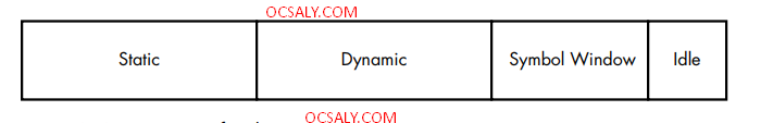
Transmitters responsible for filling in information for static slots do so when the cycle passes, but dynamic slots are filled in on a first-come, first served basis. All train cars are the same size and represent the time deterministic properties of FlexRay.
The symbol window isn’t normally used directly by most FlexRay devices, which means that when thinking like a hacker, you should definitely mess with this section. FlexRay clusters work in states that are controlled by the FlexRay state manager. According to AUTOSAR 4.2.1 Standard, these states are as follows: ready, wake-up, start-up, halt-req, online, online-passive, key slot-only, and low-number-of-cold starters.
While most states are obvious, some need further explanation. Specifically, online is the normal communication state, while online passive should only occur when there are synchronization errors. In online passive mode, no data is sent or received. Key slot-only means that data can be transmitted only in the key slots. Low-number-of-cold starters means that the bus is still operating in full communication mode but is relying on the sync frames only. There are additional operational states, too, such as config, sleep, receive only, and standby.
FlexRay Packet Layout
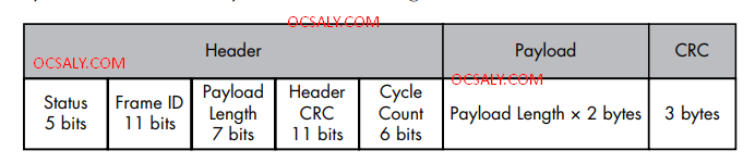
The status bits are:
• Reserved bit
• Payload preamble indicator
• NULL frame indicator
• Sync frame indicator
• Startup frame indicator
The frame ID is the slot the packet should be transmitted in when used for static slots. When the packet is destined for a dynamic slot (1–2047), the frame ID represents the priority of this packet. If two packets have the same signal, then the one with the highest priority wins. The payload length is the number in words (2 bytes), and it can be up to 127 words in length, which means that a FlexRay packet can carry 254 bytes of data—more than 30 times that of a CAN packet. Header CRC should be obvious, and the cycle count is used as a communication counter that increments each time a communication cycle starts.
One really neat thing about static slots is that an ECU can read earlier static slots and output a value based on those inputs in the same cycle. For instance, say you have a component that needs to know the position of each wheel before it can output any needed adjustments. If the first four slots in a static cycle contain each wheel position, the calibration ECU can read them and still have time to fill in a later slot with any adjustments. Sniffing a FlexRay Network As of this writing, Linux doesn’t have official support for FlexRay, but there are some patches from various manufacturers that add support to certain kernels and architectures. (Linux has FlexCAN support, but FlexCAN is a CAN bus network inspired by FlexRay.) At this time, there are no standard open source tools for sniffing a FlexRay network. If you need a generic tool to sniff FlexRay traffic, you currently have to go with a proprietary product that’ll cost a lot. If you want to monitor a FlexRay network without a FIBEX file, you’ll at least need to know the baud rate of the bus. Ideally, you’ll also know the cycle length (in milliseconds) and, if possible, the size of the cluster partitioning (static-to dynamic ratio). Technically, a FlexRay cluster can have up to 1048 configurations with 74 parameters.
When spoofing packets on a FlexRay network with two channels, you need to simultaneously spoof both. Also, you’ll encounter FlexRay implementations called Bus Guardian that are designed to prevent flooding or monopolization of the bus by any one device. Bus Guardian works at the hardware level via a pin on the FlexRay chip typically called Bus Guardian Enable (BGE). This pin is often marked as optional, but the Bus Guardian can drive this pin too high to disable a misbehaving device.