
Direct-Current Motor Principles
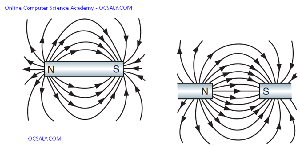
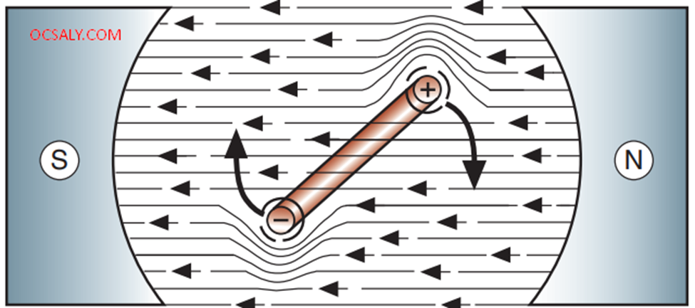
DC motors use the interaction of magnetic fields to convert the electrical energy into mechanical energy. Magnetic lines of force flow from the north pole to the south pole of a magnet
If a current-carrying conductor is placed within the magnetic field, two fields
Direct-Current Motor Principles
DC motors use the interaction of magnetic fields to convert the electrical energy into mechanical energy. Magnetic lines of force flow from the north pole to the south pole of a magnet
If a current-carrying conductor is placed within the magnetic field, two fields
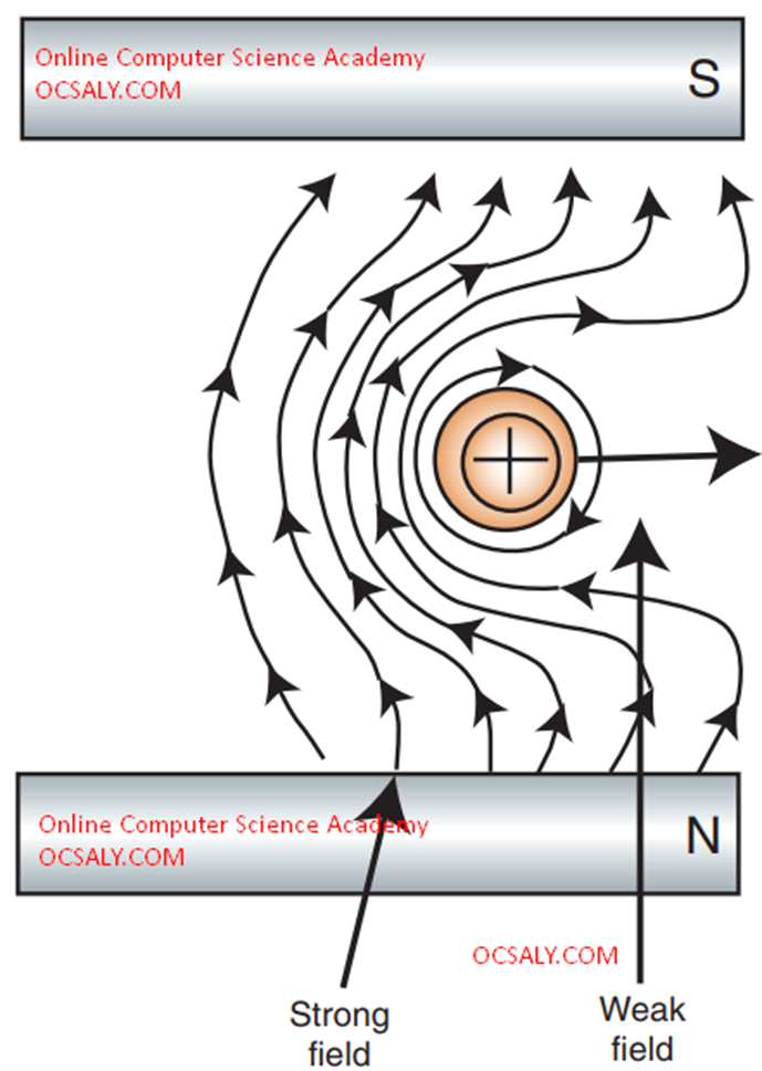
will be present. On the left side of the conductor, the lines of force are in the same direction. This will concentrate the flux density of the lines of force on the left side. This will produce a strong magnetic field because the two fields will reinforce each other. The lines of force oppose each other on the right side of the conductor. This results in a weaker magnetic field. The conductor will tend to move from the strong field to the weak field .
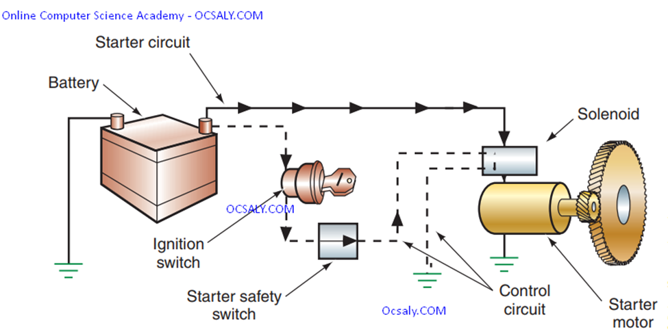
This principle is used to convert electrical energy into mechanical energy in a starter motor by electromagnetism.
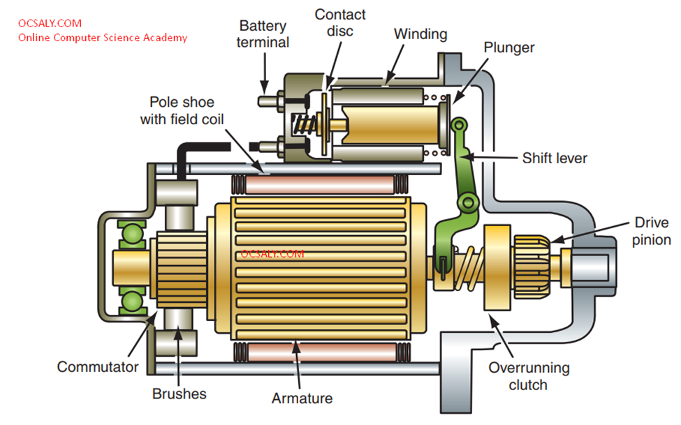
A simple electromagnet-style starter motor is shown . The inside windings are called the armature. The armature is the moveable component of the motor that consists of a conductor wound around a laminated iron core. It is used to create a magnetic field. The armature rotates within the stationary outside windings, called the field coils, which has windings coiled around pole shoes . Field coils are heavy copper wire wrapped around an iron core to form an electromagnet. Pole shoes are made of high– magnetic permeability material to help concentrate and direct the lines of force in the field assembly.
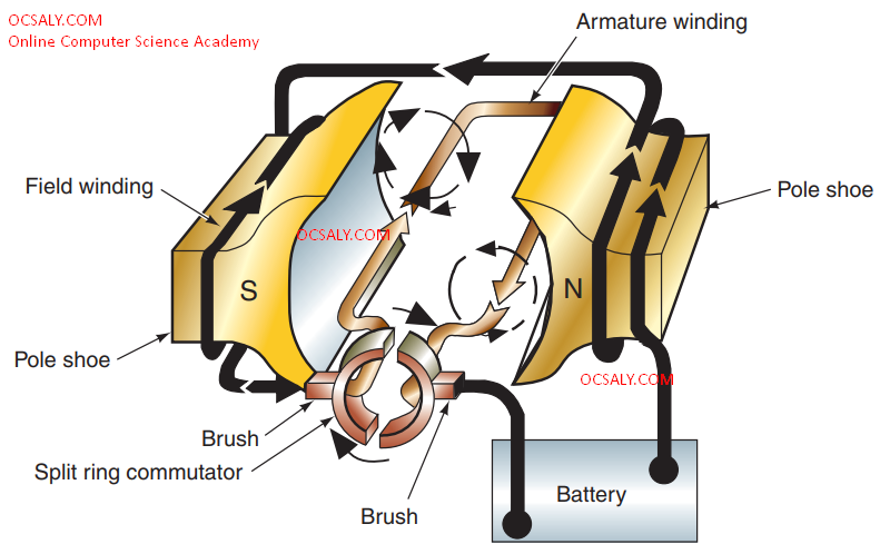
the right side at a north polarity. The lines of force move from north to south in the field. In the armature, the flux lines circle in one direction on one side of the loop and in the opposite direction on the other side. Current will now set up a magnetic field around the loop of wire, which will interact with the north and south fields and put a turning force on the loop. This force will cause the loop to turn in the direction of the weaker field. However, the armature is limited in how far it is able to turn. When the armature is halfway between the shoe poles, the fields balance one another. The point at which the fields are balanced is referred to as the static neutral point. For the armature to continue rotating, the current flow in the loop must be reversed. To accomplish this, a split-ring commutator is in contact with the ends of the armature loops. The commutator is a series of conducting segments located around one end of the armature. Current enters and exits the armature through a set of brushes that slide over the commutator’s sections. Brushes are electrically conductive sliding contacts, usually made of copper and carbon. As the brushes pass over one section of the commutator to another, the current flow in the armature is reversed. The position of the magnetic fields are the same. However, the direction of current flow through the loop has been reversed. This will continue until the current flow is turned off.
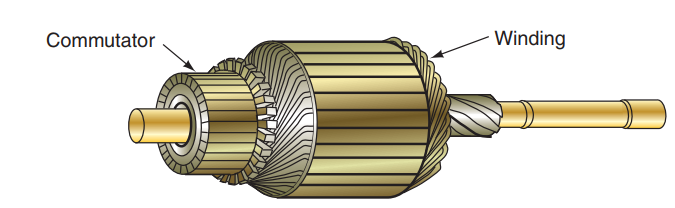
A single-loop motor would not produce enough torque to rotate an engine. Power can be increased by the addition of more loops or pole shoes. An armature with its many windings, with each loop attached to corresponding commutator sections, is shown. In a typical starter motor there are four brushes that make the electrical connections to the commutator. Two of the brushes are grounded to the starter motor frame and two are insulated from the frame. Also, the armature is supported by bushings at both ends.